WHITE PAPER

Building a Hidden Network

Why Network Cloaking is the Future of OT Network Protection
Download PDF

TL:DR

The cybersecurity landscape for Operational Technology (OT) networks is evolving, driven by an increasingly complex threat environment powered by AI and nation-state hackers. Asset owners also face the inherent vulnerabilities of industrial systems. Traditional, perimeter-focused security models, heavily reliant on hardware-based firewalls, are proving increasingly inadequate against sophisticated, AI-powered attacks and the pervasive challenge of unpatchable legacy infrastructure.

A fundamental shift towards network cloaking and Zero Trust principles is not merely an option, but an imperative for robust OT protection. By rendering critical assets invisible, enforcing granular access controls, and providing a virtual air gap and microsegmentation, these advanced software-defined approaches offer a proactive, resilient, and operationally viable defense.

A comprehensive analysis demonstrates that solutions like BlastWave’s BlastShield decisively overcome the limitations of conventional hardware firewalls, delivering superior security, simplified management, and a significantly lower total cost of ownership. This analysis leaves no doubt that cloaking and Zero Trust represent the necessary path forward for safeguarding critical industrial operations.

The Evolving Threat Landscape in Operational Technology (OT)

Operational Technology (OT) networks, which control and monitor physical processes, face a unique and rapidly escalating array of cyber threats. Understanding the distinct characteristics of these environments and the growing sophistication of adversarial tactics is crucial for developing effective defense strategies.

Unique Characteristics and Vulnerabilities of OT Networks

OT networks are fundamentally distinct from traditional Information Technology (IT) networks, as they manage and control physical processes through specialized protocols and devices. These include Programmable Logic Controllers (PLCs), Human-Machine Interfaces (HMIs), and Supervisory Control and Data Acquisition (SCADA) systems, all engineered for real-time operations and high availability. Even slight delays or disruptions in these systems can have catastrophic consequences.

A paramount difference lies in the core priorities: OT environments prioritize safety and continuous availability above all else, often superseding data confidentiality and security. Operational downtime in these critical infrastructures can result in substantial financial losses, widespread service disruptions, physical injuries, or even loss of life.

This fundamental divergence in priorities creates a significant challenge when attempting to apply IT-centric security solutions to OT. Traditional IT security practices, such as frequent patching and vulnerability scanning, are designed for IT’s priority stack. When directly applied to OT, they often cause unacceptable disruption or fail to integrate with the unique constraints of industrial control systems. This inherent conflict leads to a reluctance to implement security measures that might jeopardize uptime, resulting in delayed updates and a stagnant security posture. Any effective OT security solution must therefore be purpose-built to align with OT’s unique operational constraints and priorities, as retrofitting IT solutions without this fundamental understanding is often destined for failure. A solution that inherently minimizes disruption and simplifies management will achieve far greater adoption and success in OT environments.

A significant challenge stems from the widespread prevalence of legacy OT systems. Many of these assets are decades old, running on outdated operating systems like Windows 7 or XP, and relying on vendor-locked hardware. These systems frequently lack modern security features, are prohibitively difficult or expensive to upgrade, and often no longer receive vendor support. Crucially, these older systems often cannot be patched or updated without incurring significant operational downtime, rendering them perpetually vulnerable to known and unknown exploits.

This pervasive presence of decades-old, unpatchable, and unsupported legacy systems means these systems are not just temporarily unpatched; they often cannot be patched at all due to their age, proprietary nature, or lack of vendor support. This directly gives rise to “forever-day” vulnerabilities, meaning these security flaws will persist indefinitely. The long operational lifecycle of OT equipment ensures that these vulnerabilities remain a permanent, unmitigated attack surface. Consequently, traditional security models that rely heavily on regular patching are inherently insufficient for a significant portion of the OT landscape

A truly robust OT security solution must provide a compensatory control, effectively acting as a “virtual patch,” to shield these vulnerable systems without requiring direct modification or operational downtime

The Growing Sophistication of Cyber Threats

The increasing convergence of IT and OT networks, driven by advancements in AI and the Internet of Things (IoT), has blurred boundaries between these two domains. While offering efficiency benefits, this convergence simultaneously eliminates the historical “air gap” that once protected OT, exposing industrial systems to IT vulnerabilities and direct internet connectivity, significantly expanding the overall attack surface. This integration, while beneficial for efficiency and enhanced analytics, simultaneously dismantles the traditional “air gap” that historically safeguarded OT systems, exposing them to IT vulnerabilities and the internet, creating a significantly expanded and inherently more complex attack surface.

The benefits of convergence come with a steep increase in risk if not managed with a fundamentally different security approach. Security solutions for converged IT/OT environments cannot simply be IT solutions extended to OT; they must be purpose-built to handle the unique sensitivities of OT while securing the new IT/OT interfaces, specifically addressing lateral movement and initial access vectors that exploit this convergence.

A staggering statistic reveals that over 70% of successful breaches now leverage lateral movement techniques, including ransomware, malware propagation, credential harvesting, remote services exploitation, and “living off the land” tactics. Attackers, once inside the perimeter, move laterally to escalate privileges, access sensitive data, and deploy payloads, often remaining undetected for extended periods, averaging 95 days. This high percentage of breaches involving lateral movement indicates that traditional perimeter defenses are insufficient. The “inside is trusted” model is broken, necessitating a shift to internal segmentation and continuous verification.

Artificial Intelligence (AI) is rapidly transforming the threat landscape. Attackers are increasingly employing AI for automated reconnaissance, enabling them to swiftly scan networks, identify open ports and services, collect open-source intelligence (OSINT), analyze misconfigurations, and meticulously map out infrastructure. This reconnaissance dramatically accelerates what was previously a time-consuming manual process, making critical infrastructure vulnerable to AI algorithms that can quickly identify and exploit weaknesses. This evolution of attack capabilities renders traditional perimeter defenses, which often rely on detecting known threats or acting after reconnaissance has occurred, increasingly insufficient. A proactive defense that prevents reconnaissance altogether, effectively “blinding” the attacker, becomes paramount, shifting the strategy from a reactive detection-and-response model to a proactive prevention model at the earliest possible stage of the cyber kill chain.

A proactive defense that prevents reconnaissance altogether,effectively “blinding” the attacker, becomes paramount.

Reconnaissance is the crucial preliminary phase of any cyberattack, where attackers gather vital information about a target system’s vulnerabilities. Therefore, breaking the MITRE ATT&CK chain at its earliest stages, specifically the Discovery phase (Tactic TA0102), is paramount for effective OT defense. The strategic importance of this early disruption cannot be overstated. In OT, where downtime and physical impact are critical, preventing an attack from even starting (by denying reconnaissance) is far more valuable than detecting it during the mid-attack phase. This shift in the defense paradigm from containment to preemption provides a significant strategic advantage.

A proactive defense that prevents reconnaissance altogether, effectively “blinding” the attacker, becomes paramount.

A New Paradigm: Network Cloaking for OT Security

Network Cloaking delivers the first security architecture that can provide AI-resistant solutions for OT.

In Plain Terms

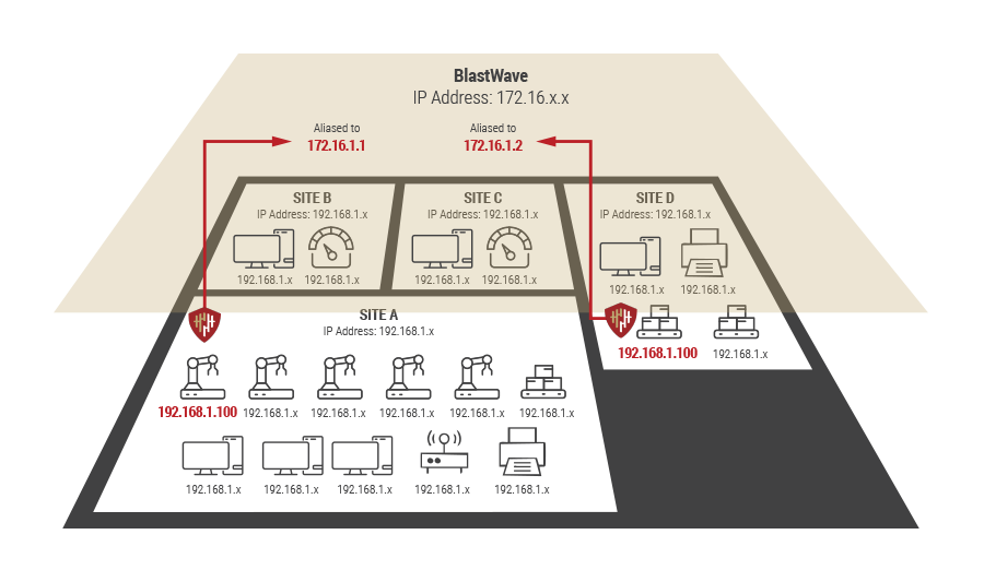
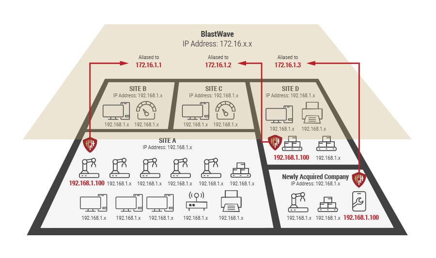
Cloaking software creates a “secure virtual network overlay” that runs on top of your existing OT network. It makes devices completely invisible unless the user is pre-approved. Here’s how it functions:

1. Secure Overlay Network

  • Cloaking software sets up a virtual address space and routing layer.
  • It operates independently of your physical IP structure like a private network map

2. No Device Exposure by Default

  • Devices behind the cloaking layer do not respond to ICMP, ARP, or port scans.
  • IPs, MACs, and services are hidden, not broadcasted or advertised.

3. Access Requires Mutual Authentication

  • A client must authenticate first using certificates and MFA.
  • Only after successful verification does the tunnel form and access routes become available

4. Built-in Microsegmentation

  • Users are allowed to see only the assets assigned to them.
  • All other assets remain cloaked, even from other verified users.

5. Encrypted Point-to-Point Communication

  • Once connected, data moves through a fully encrypted tunnel
  • No traffic is routed over traditional paths. No ARP, no broadcast, no lateral exposure.

Where It Is Installed?

Cloaking software is not installed on OT devices. Instead, it runs on trusted systems such as:

No Network Rebuild Needed

Cloaking is a software overlay — not a replacement for your existing network.

What Happens to Unauthorized Traffic?

If a user or device isn’t authenticated:

Scalability and Simplicity

Cloaking is designed for large, distributed OT environments:

Table : Building a Network Cloaking Overlay: Side-by-Side Comparison

Traditional OT Network

With BlastWave Network Cloaking Overlay

Same IPs across sites: Multiple sites often use the same IP ranges (e.g., 192.168.1.x), causing conflicts.

Same internal IPs retained: Sites keep their existing IPs; no re-IPing required.

Manual fixes required: Admins must manually configure firewalls and NAT for communication between overlapping addresses.

Overlay network created: A secure overlay is set up using 172.16.x.x, mappingeach site to a new reachable address.

Firewall + NAT at every site: Each site must handle its own external access rules and firewall policies.

Centralized NAT-aliasing: Devices are aliased (like NAT) to new addresses and accessed through a unified BlastShield mesh.

Slow configuration: Changing IPs or setting up NAT/firewalls across many devices can take weeks or months.

Fast setup via API: Devices are imported via API (from asset discovery tools), and overlay mapping is automated.

High admin effort: Each device’s address may need to be manually updated for communication or remote access.

DNS-based access: External systems connect using overlay DNS names, not IPs; internal addresses stay private.

Difficult to scale: Supporting hundreds of sites or thousands of devices requires constant manual upkeep.

Easily scales to thousands: BlastShield maps tens of thousands of devices across hundreds of sites in days.

Limited visibility: Admins must know and maintain internal IPs across every site.

Simplified management: Admins only manage overlay addresses and names exposed to external systems.

Network Cloaking:
Foundational Technologies and How It Works

Understanding BlastShield’s Network Cloaking and Secure Overlay Technology

A secure overlay is a virtual network fabric constructed logically on top of an existing physical network infrastructure, abstracting the underlying hardware and topology. Unlike traditional flat or physically segmented networks, an overlay creates a programmable, encrypted,and authenticated communication path between designated endpoints, regardless of their physical location or the intervening network segments.

In practical terms, a secure overlay takes the internal IP addresses of all devices on the network and maps them to a different addressing schema, forcing all traffic to and from the devices to pass through the device that is routing traffic for the OT network (in this case, the BlastShield Gateway). BlastShield creates a mesh between all gateways in the secure overlay, and individual users authenticate themselves to the Orchestrator for full mesh connectivity.

This virtualized approach enables the dynamic establishment of secure tunnels or encrypted paths, where all data traffic is encapsulated and cryptographically protected, ensuring confidentiality and integrity. The “secure” aspect of the overlay mandates strong mutual authentication of endpoints and robust encryption (e.g., AES-256) for all data flowing within the overlay, effectively creating a private, trusted communication channel over a potentially untrusted public or corporate network.

The concept of a secure overlay is inextricably linked with network cloaking. By encapsulating and encrypting traffic and dynamically establishing communication paths only between authenticated and authorized devices, the secure overlay effectively “cloaks” or hides the existence of endpoints, services, and even the internal network topology from unauthorized entities. Only devices that are part of the overlay, have been authenticated, and are specifically authorized for a particular communication flow can “see” and interact with other overlay participants.

Any unauthenticated or unauthorized actor attempting to scan the network or probe for vulnerabilities will not detect the cloaked rvices or devices. Cloaking significantly reduces the attack surface by making critical assets virtually invisible to anyone not granted explicit, secure access.

Distinction from Traditional Firewalling and Access Control

While traditional firewalls primarily function by enforcing access control based on predefined rules, determining which specific types of traffic are permitted or denied, network cloaking alters an attacker’s perception of the network. Instead of merely filtering traffic, it actively conceals the network infrastructure itself. A cloaking system does not respond to network scans (unlike a firewall system, which presents a visible interface), rendering the devices behind it undiscoverable and unanalyzable, thereby preventing the exploitation of both known and zero-day vulnerabilities.

This distinction highlights a significant evolution in cybersecurity strategy. Traditionalfirewalls operate within a framework wherethe network, or its services, are inherentlyvisible to an attacker. Their role is to inspecttraffic and make a binary decision: allow ordeny. An attacker, having identified a target,can still attempt to exploit known vulnerabilities or misconfigurations. Network cloaking,conversely, seeks to make the target invisiblefrom the outset, representing a fundamentalshift from a “detect and block” paradigm to a“hide and prevent discovery” paradigm. It signifies that modern cybersecurity approachesare increasingly embracing preemptivemeasures to reduce the attack surface beforeany malicious activity can even commence,thereby bolstering overall security by preventing the crucial initial reconnaissance phaseof most attacks.

Technology Used in BlastShield’s Network Cloaking

Network Address Translation NAT) for Obscurity

Network Address Translation (NAT) is a fundamental networking method that enables a public Internet Protocol (IP) address to represent computers residing within a private IP network. It functions as a critical intermediary, acting as both a translator and a bridge, to manage communication for all devices within a private network as they interact with the public internet. NAT operates at Layer 3, the network layer, of the OSI model.

BlastWave’s implementation of NAT for network cloaking results in several key deliverables:

  • Concealment of Internal Structure: NAT ensures that sensitive information, such as private internal addresses and the overall internal network topology, is not exposed to the public Internet. The internal network is a “stub domain,” where all traffic is localized and remains internal.
  • Eliminating IP Overlap Issues: All traffic for each device in the overlay must pass through the BlastShield gateway and is internally mapped to its overlay address by a combination of internal IP address and MAC address. A private IP address (10.1.1.1) or subnet (10.1.1.x) address can be reused by multiple devices on the overlay network, not only at multiple locations, but even on the same local network. In scenarios where devices come with pre-installed IP addresses, this capability can dramatically simplify and accelerate OT deployments.
  • Names, not addresses are commonly used to connect to devices: To simplify connectivity within OT environments, BlastShield assigns DNS names as part of the overlay, and administrators configure their applications to connect to device names (like camera.1stfloor.mybusiness.com) rather than needing to remember the IP addresses of thousands of devices on the OT network.

NAT’s fundamental purpose was to conserve IP addresses. However, its design inherently establishes a barrier between internal private addresses and the public internet, rendering internal devices less discoverable. This “hiding” effect, while a secondary benefit rather than a direct security feature, is weaponized in network cloaking.

Security in networking often emerges from the synergistic application of various technologies, some of which provide indirect advantages. While “security by obscurity” is generally viewed as an insufficient standalone defense, when combined with other robust security measures, the obscurity provided by NAT becomes a valuable component of a multi-layered cloaking strategy. It effectively reduces the initial attack surface, compelling attackers to expend greater effort merely to identify potential targets before they can even attempt to exploit vulnerabilities.

Different variants of NAT (Table below) offer specific functionalities that contribute to network obscurity

NAT Type

Description

Cloaking Contribution

Use Case

Static NAT (SNAT)

Assigns a fixed, one-to-one mapping between a private IP address and a public IP address.

Provides a consistent public face for a specific internal device, while still hiding its private IP address from direct external view

Useful for devices requiring continuous, uninterrupted external access, such as web servers or security cameras.

Overlapping NAT

Used when an internal network uses registered IP addresses that are also in use on another network. The router maintains a lookup table to map these overlapping addresses to unique, registered IP addresses

Resolves IP address conflicts while maintaining internal network functionality, indirectly obscuring the true (conflicting) internal IP space from external networks.

Scenarios where two networks with overlapping IP address ranges need to communicate with each other.

Layer 2 Forwarding andSegmentation for Isolation

Layer 2 segmentation is a networking strategy that involves dividing a network into multiple distinct segments at the data link layer (Layer 2) of the OSI model, typically using Virtual Local Area Networks (VLANs). VLANs enable the logical grouping of devices to communicate as if they were physically located on the same network, regardless of their actual physical location.

The mechanisms of Layer 2 forwarding and segmentation contribute to network isolation and, indirectly, to cloaking:

  • VLANs (Virtual Local Area Networks): VLANs are central to Layer 2 segmentation, enabling the creation of logically separate networks within a single physical infrastructure. By assigning a distinct VLAN ID to specific groups of devices, network administrators can effectively isolate traffic, thereby enhancing security and mitigating network congestion. Each VLAN operates independently, which simplifies network management and contains broadcast domains, preventing broadcast traffic from propagating across the entire network.
  • MAC Address Tables: Network switches play a pivotal role in Layer 2 segmentation by directing data traffic based on Media Access Control (MAC) addresses. Switches maintain a MAC address table that maps the unique MAC addresses of devices to their corresponding VLANs and switch ports. This mechanism ensures that packets are efficiently forwarded only to their intended recipient within a given segment, minimizing unnecessary network traffic and offering a foundational layer of security.
  • VLAN Tagging: The process of VLAN tagging involves appending a VLAN ID to the header of each Ethernet frame. When a packet traverses the network, switches read this VLAN ID to determine the appropriate forwarding action, restricting the packet’s movement exclusively to those ports that share the same VLAN ID, thereby isolating and directing traffic precisely within its designated segment. Trunking protocols, such as IEEE 802.1Q, facilitate the transport of VLAN information between switches, allowing multiple VLANs to coexist on a single physical link and optimizing network resource utilization.

BlastWave leverages a capability called Port Isolation Mode (also known as Protected Port or Private VLAN Edge), a Layer 2 feature implemented on network switches to enhance security by preventing direct communication between specific ports within the same VLAN.

While seemingly counterintuitive to the fundamental purpose of a VLAN (which is to allow devices within the same broadcast domain to communicate), port isolation strategically restricts local forwarding to mitigate insider threats, prevent specific attack vectors, and enforce granular microsegmentation at the access layer.

For a network engineer accustomed to traditional VLAN configurations, understanding port isolation requires a shift in perspective from broad broadcast domains to highly restricted peer-to-peer communication within a segment. Unlike standard VLAN ports, where all member ports can communicate with each other, ports configured in isolation mode cannot directly send frames to other isolated ports within the same VLAN. Their only allowed communication path is typically with “uplink” or “promiscuous” ports on the same switch, which, in the BlastShield microsegmented network, is the BlastShield Gateway. A device connected to an isolated port can reach the broader network (via the BlastShield) but cannot directly communicate with another device connected to a different isolated port on the same switch, even if both are in the same VLAN and IP subnet.

In essence, port isolation mode is a surgical Layer 2 security mechanism that allows network engineers to enforce fine-grained logical separation between endpoints residing within the same broadcast domain, significantly enhancing the security posture by limiting lateral communication and reducing the attack surface at the very edge of the network.

Layer 3 Routing and VPNs for Traffic Forwarding

Layer 3 routing forms the backbone of inter-network communication, responsible for forwarding data packets between disparate networks based on their respective IP addresses. Routing protocols are integral to this process, exchanging information to construct and maintain routing tables, which in turn dictate the optimal paths for packets to reach their intended destinations.

Several Layer 3 principles apply to network cloaking:

  • Virtual Private Networks (VPNs): VPNs establish secure, encrypted tunnels over public network infrastructures, effectively extending a private network across a shared, untrusted medium. A VPN client encrypts data before transmission and sends it through this secure tunnel to a VPN server, which then decrypts the data and forwards it to its ultimate destination on the internet
  • Data Encryption: Within the VPN tunnel, data encryption occurs using robust cryptographic algorithms, such as AES, before transmission. Encryption ensures that only authorized parties possessing the correct decryption key can access and interpret the original, intelligible data, rendering the content of the traffic unintelligible to any unauthorized entity that intercepts it, effectively cloaking its meaning
  • Routing Policies: Routing policies constitute a set of rules that govern the path data packets take through a network. They empower administrators to exert granular control over traffic flow, prioritize specific types of traffic, and reroute data to circumvent network failures or congestion.

Software-Defined Networking (SDN) for Dynamic Site-to-Site Secure Communications

Software-Defined Networking (SDN) represents an innovative architectural paradigm that fundamentally decouples the network control plane from the data plane. This architectural separation centralizes network intelligence within a software-based controller, enabling more flexible, efficient, and automated network management through programmable interfaces and Application Programming Interfaces (APIs).

SDN’s core principles and capabilities are highly conducive to implementing dynamic network cloaking strategies:

  • Dynamic Network Segmentation: SDN empowers organizations to create and adjust network segments on the fly, eliminating the need for manual reconfiguration of hardware devices. This dynamic control enables rapid changes to network configurations, facilitating swift adaptation to evolving business requirements or emerging security threats.
  • Centralized Policy Enforcement: The SDN controller functions as the “brain” of the network, offering a logically centralized view and the inherent capability to reprogram the forwarding plane at any given moment. This centralized control enables the consistent enforcement of security policies across the entire network infrastructure, including the dynamic adjustment of firewall rules and access controls in real-time.
  • Real-Time Adaptability: The programmable nature of SDN allows for real-time adjustments to network parameters in response to changing traffic demands or newly identified threats. Network cloaking strategies can be dynamically updated to counter novel reconnaissance techniques or evolving attack patterns, moving beyond the limitations of static firewall rules.
  • Virtual Network Creation: SDN facilitates the creation of virtual networks that can effectively segment different types of traffic, thereby enhancing security and reducing network congestion. These virtual networks can be specifically designed to isolate critical systems or sensitive data, preventing unauthorized access and lateral movement within the network.

Traditional network security, including rudimentary cloaking methods, often relies on static configurations and predefined rules. SDN’s core principle of decoupling the control plane from the data plane and centralizing network intelligence fundamentally transforms cloaking from a static defense into a dynamic, adaptive capability. Instead of fixed firewalls, SDN enables real-time reconfiguration of network behavior.

Software-Defined Perimeter for Dynamic Secure Remote Access

A Software-Defined Perimeter (SDP) represents a highly dynamic, identity-driven approach to network security that fundamentally reverses the traditional model of network security. Instead of connecting users to a network and then attempting to secure internal resources with firewalls, an SDP directly and securely connects a user to a specific application or resource. It operates on the principle of “never trust, always verify,” building a unique, one-to-one encrypted segment for each authorized user-to-resource connection.

This architecture is composed of key logical components: an SDP Controller (the brains, enforcing policy based on identity and device posture), Initiating Hosts (the client devices requesting access), and Accepting Hosts or Gateways (the servers or network segments hosting the applications).

When an Initiating Host attempts to access a resource, it first authenticates itself and its device posture with the SDP Controller. The Controller grants access based on pre-defined policies that incorporate user identity, device, location, and other contextual attributes. Crucially, if access is approved, the Controller then instructs both the Initiating Host and the Accepting Host/Gateway to establish a mutually authenticated, encrypted tunnel. This connection is dynamic and ephemeral, created only for the duration of the session and between the specific authorized endpoints required for the particular application. Network exposure does not occur until after the user identity and authorization are successful.

Network cloaking builds from the inherent capability of an SDP. Because an SDP operates on a default-deny principle, any application, server, or resource protected by it remains invisible and inaccessible to any unauthorized entity. Unlike traditional networks, where services might broadcast their presence or leave open ports waiting for connections, an SDP-protected resource simply does not respond to unauthenticated or unauthorized probes. Technologies like Single-Packet Authorization (SPA) can be employed, where the client sends a cryptographically signed packet to the SDP gateway before any ports are opened. If the packet is not valid, the gateway remains “dark” and unresponsive, meaning an attacker performing reconnaissance (e.g., port scanning, network mapping) on the broader internet or even within a compromised segment of the underlying network would not detect the presence of the SDP-protected resources. The SDP effectively creates a “Dark Network” around the protected assets, significantly reducing the attack surface by making them undetectable until identity and context are fully verified.

Feature/Aspect

Software-Defined WAN (SD-WAN)

Software-Defined WAN (SD-WAN)

Primary Goal

Optimize WAN connectivity, application performance, and cost.

Reduce attack surface, enforce Zero Trust, and control granular access

Focus

Network-centric: How traffic flows across the WAN.

Identity/Application-centric: Who or what can access specific resources?

Visibility

Makes the WAN more visible to administrators for performance.

Makes applications and resources invisible to unauthorized users.

Network Access

Connects sites or users to the network.

Connects users and devices directly to applications and resources, not the network.

Initial Trust

Assumes a site/VPN tunnel is trusted once established

Assumes no trust by default; verifies every connection request.

Primary Beneficiary

IT/Network Operations (performance, cost, agility).

Security Operations (threat reduction, compliance, granular control)

Architectural Layer

Primarily Layer 3 and above (routing, application awareness).

Primarily Layer 3-7 (authentication, authorization, application access)

Building a Network Cloaking Overlay

How does Network Cloaking build a secure overlay? Let’s start with a traditional multisite network, where a local administrator configures devices without corporate guid-ance, resulting in overlapping addresses.

In this OT network (see Diagram 1 right), we have four sites, all of which use the same IP address range (192.168.1.x), a configuration commonly found in SMB WAN routers and firewalls. Several devices share the same IP addresses, which means that the OT administrator must take steps to enable these sites to communicate with each other without issues.

  1. In many OT networks, administrators deploy a firewall at each site and implement dynamic NAT for most devices. At the same time, externally reachable devices employ static NAT mappings to connect to public sites. If the number of externally addressable devices is significant, the configuration task can take weeks or months for an OT network with thousands of devices
  2. Each site could manually change the IP ranges and addresses of all its devices, a process that could take months or even years.
Diagram 1

With BlastWave, a Network Cloaking overlay shortens this entire process by creating an overlay network (see Diagram 2 right).

In a secure overlay network, each site retains all of the “internal” addresses exactly as configured. The administrator creates an overlay network using the 172.16.x.x subnet, and each device in each location is aliased (aka NATed) to a new address advertised as reachable to the BlastShield mesh network.

The devices are typically imported via an API into the BlastShield system (from an asset discovery solution), and the addressing and naming can be automated. Now, the only changes needed for external systems or remote access users are that they connect to the overlay DNS name of the device or system, rather than an IP address. Changes by the administrator to the overlay addresses or even the internal address of a device are transparent to users.

For the OT administrator, changing a few control systems (which can be fed by an export from the BlastWave Orchestrator), device addressing configurations, and informing the users of the DNS name to connect to is a vastly preferable scenario than needing to change thousands of devices. In real-world settings, BlastShield ingested tens of thousands of devices across hundreds of sites into an overlay network within a matter of weeks.

Diagram 2

Orchestration and Management

The BlastShield Orchestrator is used to create, modify, and remove all Users, Agents, and Policies within the BlastShield Network. Only users with authorized privileges can access and use the Orchestrator. As discussed earlier in this document, the Orchestrator acts as a ZTA policy engine (PE) and policy administrator (PA). Rather than configuring subnets, ACLs, and VPNs, BlastShield makes it easy to set up granular access by creating and managing Users, Agents, Groups, Policies, and Proxies.

Step 1: Add a New Agent in the Orchestrator

  • Click on “Agents” in the “Manage” menu in the left sidebar, then click the red “Add New Agent” button at the top right.
  • The New Agent dialogue opens. Add a name for the Agent and a DNS Hostname. The DNS Hostname is optional and can be used to identify the Agent in the BlastShield network as BlastShield runs its own DNS.
  • Then click on the red “Save and Download Invitation” button and choose the option for “Save and copy Linux/macOS installation command to the clipboard”. Click on that option to copy the command.

Step 2: Install and register the agent

  • Open a terminal session on the Linux server where you are going to install the Agent
  • Paste the command you just copied to the terminal and hit enter. This will start the software download. The software will automatically install and run.
  • The Agent will then automatically register with the Orchestrator. When the process is complete, you will see the following message in the terminal window: “Installation successful, the agent IP address is <Agent IP address>.”

Step 3: View the status of the Agent

  • Now that the installation and registration processes are complete, your Agent is up and running.
  • You can check the status of the Agent by typing the following: sudo systemctl status blastshield
  • The logs may be viewed as follows: a. sudo journalctl -u blastshield. service
  • The status of the new Agent on your server should appear as “Online” in the Orchestrator as shown in the image below

For more detailed instructions on implementation for Linux, Windows and MacOS, visit support.blastwave.com.

BlastWave also provides professional services and phone support.

BlastShield Licensing and Pricing

BlastWave licenses the use of its downloadable BlastShield software and access to its cloudbased Orchestrator on a per agent basis. Pricing is based on the number and type of devices protected by BlastShield, represented by the number of installed Active Clients, Agents, and Gateways. BlastWave charges an annual licensing fee for each device depending upon the type of agent installed.

Our licensing includes access to features such as ZTNA, phishing-resistant MFA, single sign-on (SSO) support, microsegmentation, cloud orchestration, gateways, REST API, and optional on-prem orchestration.

Conclusion and Recommendations

Industry trends and Federal Government mandates are driving adoption of zero trust architectures (ZTA). Federal agencies, enterprises, and industrial companies would be wise to learn more about zero trust concepts and develop strategies to migrate to a ZTA. Recognizing the importance of improving cybersecurity controls, the U.S. has directed many security-related agencies to facilitate sweeping changes in the way they manage cybersecurity. The U.S. Office of Management and Budget issued a memorandum that set a deadline of FY 2024 for agencies to comply with sweeping new cybersecurity guidelines based on the NIST SP 800-207: Zero Trust Architecture and CISA Zero Trust Security Model Guidance.

BlastWave’s BlastShield Zero-Trust Network Access (ZTNA) solution can help organizations accelerate the migration to ZTA. BlastShield uses a software-defined perimeter (SDP) approach to ZTA that combines phishing resistant MFA, simple orchestration, granular access controls, peer-to-peer full-mesh networking, and device invisibility to provide a level of security that goes beyond zero trust standards. BlastWave radically simplifies the security stack and enables zero trust without sacrificing performance or cost.

Download the White Paper!

Learn how to implement BlastShield to comply with Zero Trust architecture requirements.

Our Privacy Policy applies.